Keeping pace with industry needs garment manufacturing machines that are today equipped with ultra-modern features which have resulted in time saving and improved uninterrupted functioning. Automatic replacement of an empty bobbin to a filled one is one such advancement which has proved its usefulness in the continuous running of the machines. Such machines may be standard single needle lockstitch machines, zigzag stitchers, button attachment, button hole machines, automatic pocket setters, embroidery machines or quilting machines, etc. These advancements provide a viable solution to frequent machine stoppages and productivity loss due to thread runout in bobbin. In the fourth article of the series on patents, authors Manoj Tiwari, Assistant Professor, NIFT, Gandhinagar and Dr. Prabir Jana, Professor, NIFT, Delhi have discussed the technological interventions done in the field of Automatic Bobbin Changers.
Bobbin thread is one integral element for sewing, playing an important role in maintaining quality of the product and higher productivity. Regular interruptions in the sewing operation due to running out of bobbin thread are a common scenario on the sewing floor as bobbins have limited thread storage capacity. While a single needle sewing machine bobbin has approximately 60 metres (thread storage for 120 ticket number thread) which takes around 10 minutes to empty (at approximately 2200 SPM), needing approximately 40 replacements in an 8-hour shift resulting in loss of work time of around 30 minutes. Though the majority of sewing machines are equipped with bobbin thread winder and filled bobbins can be kept ready as reserved for replacement as needed, still there is need of manual intervention in replacing the empty bobbin. There have been continuous efforts in the direction of automated bobbin replacement and many of them are now commercially used, however automatic bobbin changing is still considered as a relatively less explored area.
In the conventional method, the bobbin replacement in the sewing machine is done manually for which the machine has to be stopped causing loss of productivity and at the same time affecting the operator’s concentration.
A standard sewing machine bobbin has approximately 60 metres of thread storage, which takes around 10 minutes to empty 2200 SPM, requiring near-about 40 replacements in an 8-hour shift resulting in loss of work time of around 30 minutes.
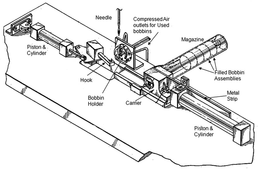
One of the initial developments in this area was done by Ivanhoe Research Corporation, USA way back in 1968, for which a patent (US Patent No. 3376838) was awarded for developing Bobbin Changer for Sewing Machines. The developed device equipped with a magazine, which stores the filled bobbins with bobbin cases was suitable to be used in the conventional sewing machines. In the process a carrier was used to take out the empty bobbin from the bobbin holder and replaced by a filled bobbin from the magazine. The bobbin replacement mechanism was controlled electrically by actuating the different operating components in a sequence.
Figure 1, outlines how the threaded bobbins with bobbin case are arranged in the magazine (a tubular container) and are kept aligned with the help of a coil spring fixed at one end of the container. The filled bobbins with bobbin case are received by the carrier at one end of the magazine. The carrier includes an opening which receives the filled bobbins from the magazine and is kept aligned in the correct position with the help of a metal strip. When the carrier moves towards the bobbin holder, the opening of the magazine is kept closed by the same strip to prevent the next bobbin assembly in the magazine from coming out. On the other end, at the opening of the bobbin holder, a hook is provided to transfer the bobbin assembly from the carrier to the bobbin holder by engaging itself to the latch of the bobbin. The hook is activated with the help of fluid controlled pistons operating in cylinders fitted on the machine frame. To remove the used bobbins from holder, a set of air jets are used.

The complete mechanism is basically a series of events controlled by three switches: Switch 1 for solenoid control to actuate the carrier as it moves from the magazine to the holder and back; Switch 2 for controlling pivoting movements of the transfer towards and away from the holder; and Switch 3 is for actuating the reciprocation of hook to engage the latch of the bobbin and inserting it into the holder.
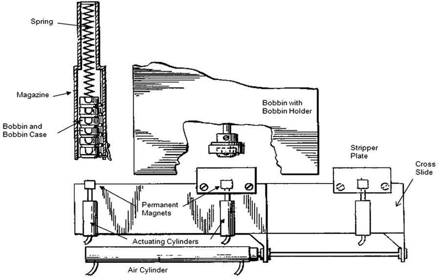
J. P. Stevens & Co. Inc., USA developed a Magnetic Automatic Bobbin Changer for Sewing Machines that was awarded patent (US Patent No. 3981256) in 1976. As shown in Figure 2, a magazine full of bobbin casings (filled bobbin and cases) is attached and positioned to the sewing machine.
In the device a cross slide bar was equipped with two magnets put at definite positions, in such a way that in one position one magnet was aligned with the magazine and the other was in front of the sewing machine bobbin holder. The magnets could be moved forward with the help of fluid operated actuators. When the bobbin was exhausted, both the magnets moved forward — one towards the bobbin holder and another towards magazine — to retract the exhausted and filled bobbin from bobbin holder and magazine, respectively. After retracting the bobbins, the magnets move back and the cross slide moves forward stopping at a position where the filled bobbin is adjacent to the bobbin holder. Then the magnet was pushed forward to deliver the filled bobbin, while the empty bobbin was withdrawn by the stripping plate and sent for rewinding through a chute. At the end of the process the cross slides move back to the initial position and ready for the next cycle.

In the year of 1977, Automatech Industries Inc. was awarded a patent (US Patent No. 4002130) for Automatic Bobbin Rewinding for Sewing Machines. The mechanism was capable of replacing the used bobbin with the newer one in the machine as well as winding of the thread on the exhausted bobbin. To maintain the continuity of the sewing operation, rewinding of the filled bobbin was done when one bobbin was in use. Some special features of the device were the capability of unwinding the leftover thread in the used bobbin before start of winding of new thread and keeping the newly inserted bobbin thread engaged to the sewing element to minimize the manual intervention.
While doing stitching on a belt of predetermined length, one cannot afford to have a join in stitching in-between, and in case the bobbin gets exhausted half way the entire stitching needs to be ripped off and a new stitching needs to be done after changing the bobbin. This is clearly a huge wastage of time, money and a big productivity loss. The solution to this problem was simply calculating the thread required for one piece and determine the number of units that can be completed from thread wound in a single bobbin, based on which the timing for automatically changing the bobbin can be set. Based on this logic two developments are patented. First was Levi Strauss & Company, USA (US Patent No. 3744442) in 1973. The device contained a cylindrical container having plurality of bobbins in a circular way. With help of a cycling mechanism, the cylindrical container could be rotated pushing the required bobbin to shuttle position to be used in stitching. To engage and disengage the cycling mechanism from the main drive of the sewing machine, a clutch was provided, which could be regulated by the control system based on the counting of stitches while sewing.
The second patent was in 1980 to the Gateway Industries, Inc. USA (US Patent No. 4223618).

In the invention the unlatching of the bobbin from the shuttle in the sewing machine and substituting the same with a filled bobbin casing is initiated automatically after a predetermined number of sewing operations are done. As shown in Figure 3, to take out the bobbin casing from the sewing machine, a latching lever is provided with a hook and a free end of a plunger. Then the removed bobbin assembly is transferred into the cavity/bobbin receptacle (Space to accommodate the bobbin casing) in a magazine. The magazine or cartridge, which is like a linear shape hollow bar, has at least one empty cavity to receive the latest used bobbin and a series of filled bobbins ready for use in a series. After receiving the used bobbin the magazine is shifted linearly in such a way that a fresh ready to be used bobbin in the magazine comes in alignment with the plunger and the shuttle shaft in the sewing machine. Then the plunger is actuated by means of a pneumatic piston in the direction to push the new bobbin casing into the shuttle of the sewing machine.
Bar-Cochva, Y. Sadeh and Y. Makover from Israel were awarded patent (US Patent No. 5143004) in 1992 for developing Sewing Apparatus including Automatic Bobbin Reloading device. The device based on optically sensing the bobbin and replacing it with a filled bobbin to resume sewing was simple in construction and could be fitted in an industrial sewing machine. The device was unique in terms of automatically reloading the bobbin whenever there was thread breakage or the bobbin was exhausted.

As shown in Figure 4, the walls of the bobbins are having optical sensing strips. To make the sensing easy and accurate, the colours of the strips were kept in contrast to the colour of the bobbin wall. The optical sensors aligned with the opening, are positioned in front of the bobbin wall to sense these strips. When the bobbin rotates, it generates the pulse, which indicates a rotating bobbin, at the same time the rate of this pulse indicates the rotational velocity of the bobbin. Whenever there is any interruption in the rotation either due to thread breakage or when the bobbin is exhausted; the sensor which is connected to a control unit gets activated to extract the used bobbin and reload a filled bobbin.
The bobbin extracting and reloading apparatus is equipped with an arm carrying an electromagnetic head. The arm is pneumatically operated and can rotate 180° with extracted bobbin casing. The arm takes out the bobbin casing from the machine and moves it to the bobbin rewinder installed nearby. The bobbin rewinder has two stations fitted on a rotatable bobbin holder turret, one is for receiving the exhausted bobbin and another is for filled/rewound bobbin. The exhausted bobbin is brought to the upper position and then the turret rotates for 180° in such a way that the filled bobbin is positioned to be collected by the arm and the exhausted bobbin moves to lower position for rewinding. The arm extracts the filled bobbin from the second station and moves to load it in the sewing machine.

Haruhiko Kinoshita from Japan can be named as the breakthrough inventor in the field of Automatic Bobbin Exchangers. In the year 1998, Kinoshita was awarded patent (US Patent No. 5775243) for developing Thread Exchanger Device for Sewing Machine.
The Thread Exchanger that can be fitted on an industrial sewing machine is equipped with a cassette having plurality of bobbin casings (Eight Bobbin Casings) along its circumference. Based on manual selection the empty bobbin assembly (bobbin and bobbin case) can be replaced with a filled bobbin assembly. As shown in the Figure 5, a cassette drive member is provided to rotate the cassette and to move it into the exchangeable position. A chuck member is provided to take the exhausted bobbin casing off from the machine and place it in one of the empty locations in the cassette, taking off the filled bobbin from the cassette and finally putting it into the sewing machine. The rotary cassette is fixed on a support plate by means of a rotary disc and index shaft.
Juki Corporation, Japan was awarded a patent (US Patent No. 5718181) in the year 1998 for inventing a Bobbin Exchanger. The device was unique in terms of lesser moving parts (less complex yet compact design), free movement and accuracy while supplying the bobbin. Adding to it an ordinary bobbin casing which is capable of being attached to most of the brands of sewing machines. Unlike the other devices (as discussed in previous patents), this device was free of grippers or clutches at the end of the arm hence it not only saves space but makes the device easy for maintenance.
The device is equipped with automatic thread removing as well as thread winding devices, which can be fitted on the sewing machine itself. As shown in Figure 6, the device consists of a base plate attached under the machine base. A carrier shaft which is parallel to the rotary shaft is fitted to the base plate. A gear is provided at one end of the rotary shaft and connected to one smaller gear, called motor gear. The motor gear receives drive from a motor capable of both forward and reverse directions. A carrier arm is also fitted to the rotary shaft, having a holder with grip mechanism at one end facing to the shuttle. To move the carrier arm up and down while loading and ejecting the bobbin, a rack and pinion arrangement is provided with help of a collar fitted with the rotary shaft. On the arc of the carrier arm, three additional mechanisms are also provided, which are named as B, C and F for Bobbin holding, Bobbin rewinding and Bobbin residual thread removing, respectively.

At the initial stage, an operator puts 2 filled bobbins at B and F positions. When starting the sewing operation, the arm takes out the filled bobbin from position B and is inserted into the shuttle. When the bobbin in use is exhausted and has some residual thread, the sewing operation gets interrupted due to which the carrier arm rotates towards the shuttle to take the used bobbin out with help of the gripping mechanism installed in the holder. The carrier arm moves with the empty bobbin from shuttle to the position B and inserts it there. The arm then moves upward and rotates towards position F to collect the filled bobbin. The arm grips the bobbin at F and moves with the filled bobbin to the shuttle. Once the filled bobbin is inserted the sewing resumes; the arm moves again towards position B and takes out used bobbin from B and moves it to F. If there is residual thread in the bobbin at F; the thread removing mechanism gets actuated thereafter the same empty bobbin is taken out by the arm and moved to position C for thread winding. Once the thread winding is done, the filled bobbin is transferred to the position B and the bobbin is ready for the next loading into the shuttle. At the time of the next sewing interruption, the used bobbin is taken out by the carrier arm and fitted into the position F for residual thread removing. In the mean time carrier arm takes out filled bobbin from position B and takes it to the shuttle. In this way the complete replenishment of used bobbin to the filled one takes place.
In the year 2001, Kinoshita Precision Industrial, Japan invented a Remote Control Bobbin Case Exchanger device and got a patent (US Patent No. 6170417, B1) for the same. The device is useful where availability of the filled bobbins is not possible within the reach of the operator and also in multi head industrial embroidery sewing machines, where pluralities of bobbins (6 to 15 bobbins in number) are used simultaneously. The main objective of the device is to provide a remote control bobbin case exchanger capable of readily exchanging bobbin cases, where the rotary bobbin is placed inaccessibly.
As shown in Figure 7, the device consists of pneumatically controlled assembly having a chuck and chuck driving member, which slides under a horizontal cam groove to carry the exhausted bobbin and take the filled bobbin from the rotary drive device. The rotary drive is equipped with a case mounting member having plurality of bobbins. The to-and-fro movement of the chuck member is controlled by the pneumatic cylinders. The rotation of the rotary drive having case mounting member is controlled by a rack and pinion arrangement.
In the year 2007, Tokai Kogyo Mishin Kabushiki Kaisha and Kinoshita Precision Industrial Co., Japan were awarded the patent (US Patent No. 0056490, A1) for developing Bobbin Exchanger Apparatus for Sewing Machine. The device is equipped with a detachable transferring mechanism for carrying bobbin grasping device from shuttle of the sewing machine to the bobbin stock section from a distance and can be used for multi head embroidery sewing machines. The transfer mechanism consists of two cams designed in such a way that one cam is part of a sewing machine and another can be fitted with the extension of sewing table.